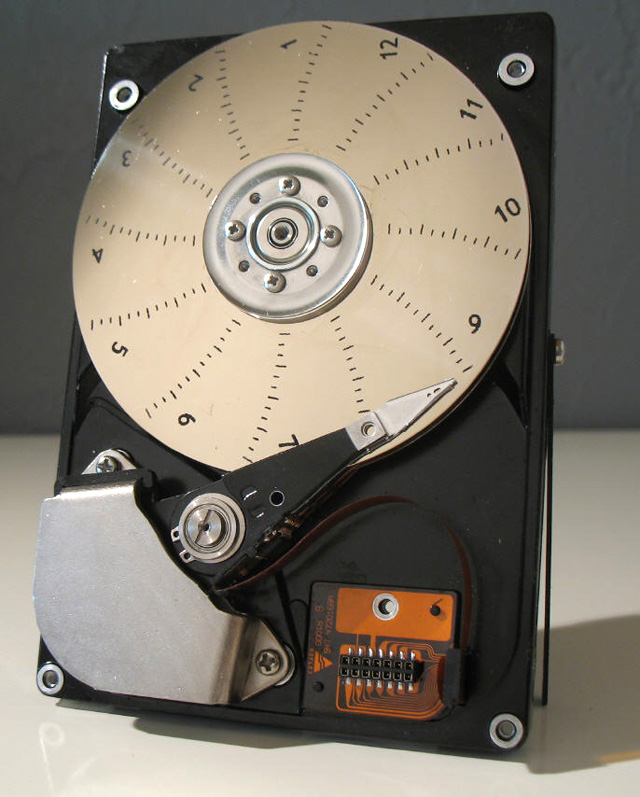
A Hard disk drive is, by itself, a nice "piece of art". It's a precise mechanism with a shinning almost perfect mirror.
I decided to keep as much as possible of the original HDD and to convert it into a working clock.
My specifications were as follows :
as little visible modifications as possible on the disk
the head arm should indicate the minutes
the rotating disk should indicate the hours
the device should be automatic on startup
the disk should be powered by any 5V coming either from a USB charger or directly from a PC USB host
a USB interface should provide access to a software to tune and setup the device (plug & play)
Time should be kept in case of a power failure
clock should be noiseless
and... a little extra :
clock should be used as a little loudspeaker
clock should speak
As you can see the result is rather cool. You will see now how to build this "HDD Still clock" from A to Z.
This video shows you the final result
It is a rather simple concept :
A phototransistor sensor and its infra red photodiode are put under the bottom platter of the disk to trigger an event any time the clock is at 12:00
The HDD motor is controled by a microcontroler and is driven either in "step by step" mode or in "brushless" mode via a power driver. This disk rotates the hours ring.
The head arm coil is voltage controled via a PWM signal, the head is thus displaying minutes
A windows PC software controls the device USB interface
Hardware
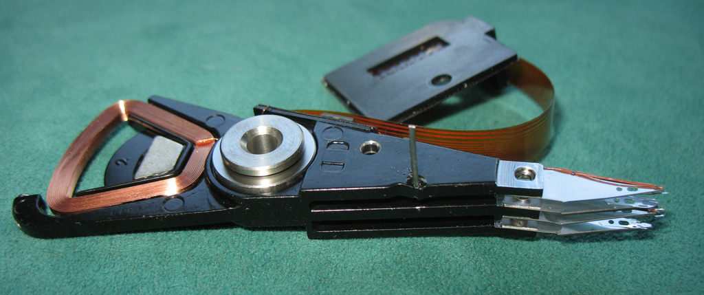
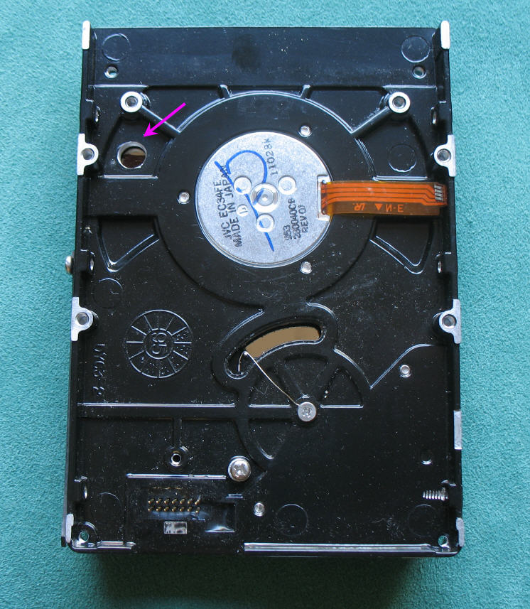
Open your HDD and remove the heads arm :
remove the upper half magnet
unscrew the the platter locker screws
unscrew the connector screw
unscrew teh screw on the central axis of the heads arm
the magnet is very strong, it is uneasy to remove it. You can use a screwdriver to help you, but beware that the coil is very fragile... and is absolutely needed for this clock.
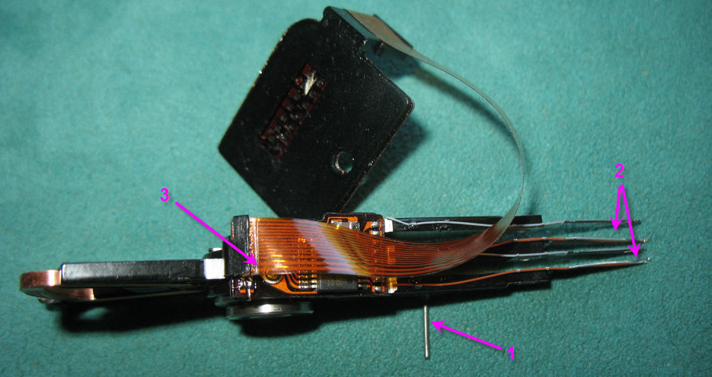
The heads arm must be equiped with a litlle torsion spring to convert it into a moving-coil galvanometer.
Wikipedia tells us that a moving-coil galvanometer is a type of ammeter: an instrument for detecting and measuring electric current. It is an analog electromechanical transducer that produces a rotary deflection of some type of pointer in response to electric current flowing through its coil in a magnetic field.
The D'Arsonval/Weston galvanometer used today is constructed with a small pivoting coil of wire in the field of a permanent magnet. The coil is attached to a thin pointer that traverses a calibrated scale. A tiny torsion spring pulls the coil and pointer to the zero position. When a direct current (DC) flows through the coil, the coil generates a magnetic field. This field acts against the permanent magnet. The coil twists, pushing against the spring, and moves the pointer. The hand points at a scale indicating the electric current
the torsion spring is dissimulated under the heads arm. It is totally not visible.
the heads arm is drilled and a piece of piano wire is epoxy glued in the hole
the heads are properly removed and their fixations are bended to avoid to touch the disk. .
You need to find the two biggest wires on the connector. They shoud be the coil connections. We will use these connections to power the coil.
The spring is done with another piece of very thin piano wire. It is fixed under the the disk and connected to the piano wire on the moving arm.
Click on the pictures to zoom
RPR220 phototransistor is soldered on the PCB and its led focusses IR beam on the bottom platter of the disk. A hole is drilled in the disk enclosure for that. A dark spot is painted on the disk to be detected easily by the sensor.
it is highly recommended to position the PCB on the disk before soldering the RPR220 sensor. Doing so will allow you to use the 4 pins holes to mark the disk enclosure and so to easily position the hole on the enclosure.
Zoom the pictures to access details. On the left side pcture you can see the half of the dark spot on the platter.
Idealy the phototransistor should fly at 6mm of the dark mark. Fine tune the pins lenghts if necessary before soldering.
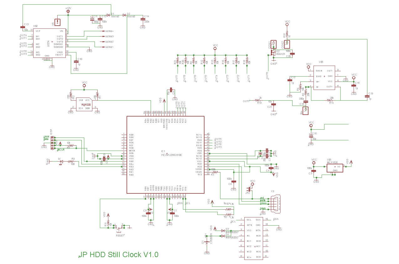
Monitoring and control electronics
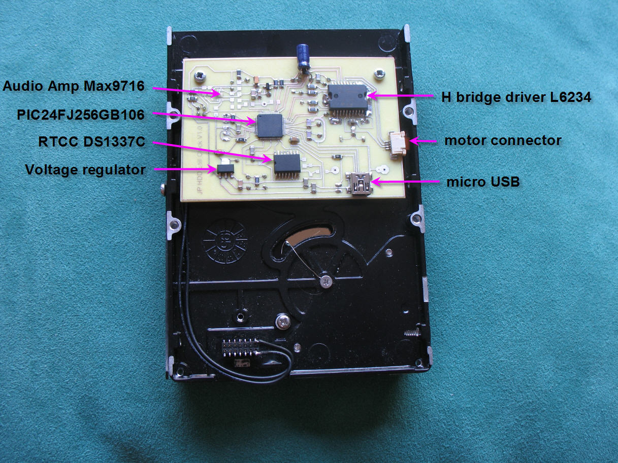
Electronics is based on Microchip PIC 24FJ256GB10. microcontroler. This 16 bits MCU has a native USB port which allows easy interface with a PC.
It has also 9 hardware PWM ports which are perfect to drive motors.
Toghether with the PIC we find :
A triple H bridge driver L6234 used to pilot the motor
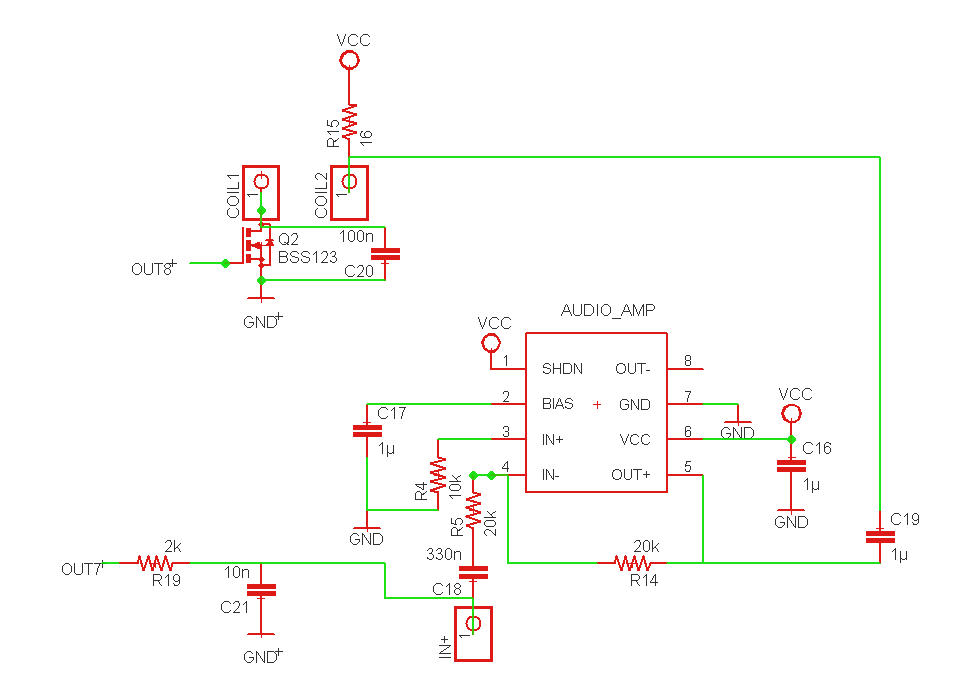
I talled you that I wanted to have my clock speak... It's an easy concept to use the "voice coil" of the arm as a loud speaker. See (listen) this video and you will understand hox easy it is. (and improve your french with hte comments )
Of course the same voice coil collects as well the minutes PWM signal. We have to "add" it with the audio signal. This is done right at the output of the audio amplifier. .
A PWM signal of the microcontroler is also abble to output a voice message directly from the clock. This will be used to have a speaking clock
to summarize :
OUT7 = "voice" PWM output of the microcontroler
OUT8 = "minutes" PWM output of the microcontroler
IN+ = external audio input
Software
The main difficulty is to run the motor. These devices are brushless Direct Current motors. If you prefer "brushless DC" or even "BLDC" motors.
You will find on internet a lot of interresting readings to pilot a BLDC. Here are my references :
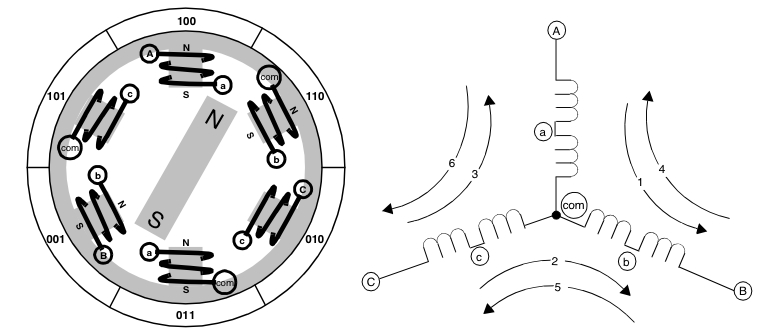
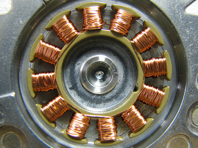
A BLDC always has two coils energized and the 3rd one "floatting". Considering the various solutions to flow the current into the coils you can get 6 stable positions. This second picture shows the motor energized on the first arbitrary position. Curent enters by A point and outputs on B point. The rotor is attracted to this stable position.
A Hard disk drive motor has more coils than this simple triphased motor. Practically I have found 24 stable positions. The basis sequence of 6 positions is thus repeated 4 times. 24 is a very convenient number for a clock
The drawing on the right clearly shows the 6 stable positions of the rotor for a triphased motor.
To run the motor I could have choosen to simply drive the motor "step by step" looping on the 24 sequence steps. This is in fact what I do when being in "clock mode" or when launching the disk rotation at startup.
But it is much more interesting to try to drive the motor in "brushless" mode.
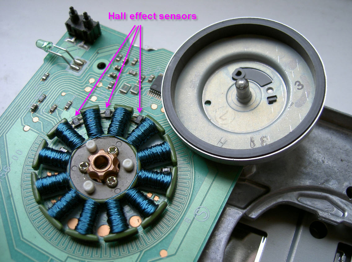
The simplest method to drive a BLDC is to have a motor equiped with hall sensors. These three sensors are positionned just in between the stator teeths and allow to trigger 3 successive stable positions of the rotor. (On the picture you can see an old floppy motor with its Hall sensors clearly visible). Note the positions of these sensors which are the same as the stable rotor positions on the above picture.
A hard drive motor does not have hall effect sensors... They use another technics to find the rotor position. This "sensorless BEFM" technics is efficient but much more complex to implement...
I have thus decided to replace the hall effect sensors by a single sensor : the RPR220 phototransistor.
This sensor allows me to check the 12:00 position of the clock and to check the stable position 6 of the rotor. The bottom platter must be carefully aligned with this stable position. I will show you latter how to do. This being done, knowing that there are 24 stable positions, you just have to know the duration of a full rotation, to divide it by 24 to get the duration of a full step. You can commutate the position n°1 when you see the dark spot and then trigger the following 23 steps in sequence. It may seem simple but bear in mind that you have to start the disk in "stepper mode" accelerate it and when the speed is high enough switch to brushless mode. It can be a little tricky mainly if you remember that the disk is a 12V one powered only with 5V...
Of course the coils are not directly powered with 5V DC but are powered via a PWM signal to limit the current into them and to tune the rotation speed.
To run your HDD Still Clock you will need to flash the PIC firmware. .hex file can be downloaded
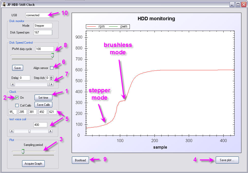
There is also a PC software to fine tune your system. accessible functions are :
time setup from the PC clock (then backed up into the RTCC)
switch from "clock" mode to "disk" mode
monitor disk speed
save an ascii file of displayed curves.
calibrate the "minutes" arm
calibrate the position of the RPR220 sensor
avanced tuning of the motor synchro (steps number increment "Adv" and fraction of step)
disk speed tuning (PWM duty cycle)
bootload button allowing to flash firmware when pressing the reset button on the board
and this board is fully plug and play, no driver is needed on the PC
You need now to design a nice "clock platter". The disk geometry is directly influencing this design.
Yo need to make a precise plan of the disk, axis positions, head arm lenght... and to report all this into a CAD software. here is my design for my old samsung disk. dxf plan
A have tested several ways to transfer this drawing on the disk.:
toner transfer method with a laminator and a laser printer ( toner transfer). Result is clean but very fragile and there is a lack of accuracy when positionning the drawing on the platter. (see picture on top of this page).
V shape engraving with my CNC mill. Result is almost perfect even though signs are are little too wide...Here is the GCode engraving file
this video has been accelerated (High speed milling)
Here is the finished platter that you have to fix on the HDD.
phototransistor calibration :
tick the checkbox . The disk will lock on the calibration position.
unscrew the platter
rotate the bottom disk until the led switches on
rotate the top platter until it shows "12:00"
screw again the platter fixations
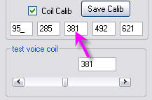
Head arm calibration :
check the box you can now move the horizontal scroll bar ( )
positon the arm to 00:00; 00:15 ; 00:30 ; 00:45 ; 01:00 and each time write the value in the adhoc text box
save these values in eeprom
example for 00:30 :
This HD video demonstrates how the clock handles hours and minutes changes !
You can zoom twice on this picture to get high res details !